The Information Train
Diomidis Spinellis
Department of
Management Science and Technology
Athens University of Economics and Business
Patision 76, GR-104 34 Athens, Greece
http://www.dmst.aueb.gr/dds/
dds@aueb.gr
Abstract
The
increased application of software-controlled digital electronics hinders the
understanding of how things work. The information train is a scientific
experiment exhibit that physically demonstrates how
computers communicate. It comprises a network in which a model Lego train acts
as a physical carrier transferring a picture's pixels from one computer to the
other. The sending end computer scans a simple picture, and directs a model
train to send that pixel to the receiving end computer. This is done by sensing
the approaching train and switching a rail junction depending on whether a
pixel is on or off. The train carries on its top a piece that rotates depending
on the train’s route, thus carrying the data between the two computers. At the
receiving end, two sensors detect the shape’s orientation allowing the
receiving-end computer to reassemble the picture bit-by-bit, pixel-by-pixel.
The receiving-end computer is a One Laptop per Child (OLPC) XO-1 machine,
programmed using EToys. This provides further opportunities
for motivated adventurous children to interact with the experiment’s
implementation.
When I was
a kid I had a pretty good idea of how most appliances in our home worked. The
phone was a circuit that physically connected the microphone at each end with
the speaker at the other end. The record player’s needle picked up the sound
from the grooves of a rotating disc and converted it to current through a
magnetic coil. Even the TV was a relatively simple affair: two electromagnets
had a ray scan the picture while it was modulated to turn parts of the screen
white.
How things
change… Nowadays to give a similarly realistic picture to our generation’s
children I have to talk about analog to digital conversion, CPUs, flash memory,
compression, psychoacoustic coding, packet routing, pixels, color perception,
and liquid crystal displays. Or lie.
Yet, there
is still value in understanding the basic principles of modern communication
technologies, even at the cost of brave simplifications, for this will seed in
our children the interest in the world surrounding them, the willingness to
explore it, and, maybe, the ambition to pursue a personally and socially
rewarding career in science and engineering.
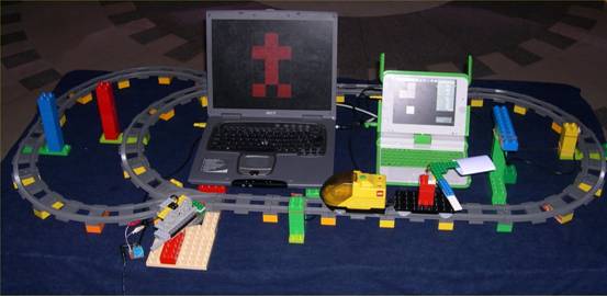
Figure 1 Experimental setup
In response to this goal, I created a scientific experiment exhibit that physically demonstrates how computers communicate with each other by setting up a network in which a model Lego train transfers a picture's pixels from one computer to the other (Figure 1). In brief, the sending end computer (on the figure’s left) scans a simple picture from left to right and from top to bottom, and directs a model train (on the front) to send that pixel to the receiving end computer (on the right). This is done by sensing the approaching train and switching a rail junction (front-left) depending on whether a pixel is on or off. The train carries on its top a horizontally-mounted L-shaped piece, hinged in a way that allows it to rotate so that it protrudes from the train’s left or right side. This part carries the data between the two computers. Depending on the track to which the junction sends the train, the train will pass close to a column on its left (red) or right hand side (blue), thereby rotating the L-piece to the corresponding direction. At the receiving end, a sensor (yellow, on the right) detects the train’s passing, and a second one (green-blue, on the front right) checks to see the shape’s orientation. Based on that input the receiving-end computer reassembles the picture bit-by-bit, pixel-by-pixel.
The exhibit
is based on readily available components. The use of a large-scale (Duplo) Lego train provides a robust, accessible, and
configurable platform to which children can easily relate to. The sending and
receiving computers are laptops. In contrast to desktop computers, these are
self-contained, and can therefore easily communicate their sending or receiving
function by placing them near the positions of the track related to it. One of
the laptops is a One Laptop Per Child (Lee 2006) XO-1
model, thus demonstrating the machine’s educational potential. The interfacing
parts are bespoke circuits based on cheap electronic components. Although the
same functionality could have been achieved using Lego-provided black-box
components, like WeDo or Mindstorms,
the chosen alternative is more open and affordable. Most modern PCs lack simple
general purpose input output ports. In particular, USB ports require complex
interfacing hardware and device drivers. I therefore repurposed ports provided
for other purposes. Nevertheless, the USB ports proved useful for providing a
relatively clean 5V supply needed to power the sensors.
Sender implementation
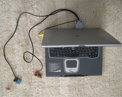
Figure 2 The
sending computer
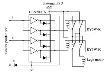
Figure 3 Sender motor
control circuit
On the
sender side (Figure
2), interfacing takes place through
the laptop’s parallel printer port. This supports eight output bits and five input
bits used for signaling conditions like “printer busy” or “out of paper”. A
motor is used to control the rail junction’s position through a rack and pinion
assembly. The motor control circuit (Figure 3) uses two of the printer port’s
output bits to control the junction’s motor, according to the following table.
|
Bit A |
Bit B |
Motor |
|
0 |
0 |
Stopped |
|
0 |
1 |
Forward |
|
1 |
0 |
Reverse |
|
1 |
1 |
Not allowed |
This is done
by using a Darlington transistor array integrated circuit (Texas Instruments
1976) to control the windings of two relays, which in turn switch
externally-supplied current to the motor. One of the relays controls the
motor’s power and the other its rotational direction. The Darlington
transistors were wired in pairs to increase their current driving capability.
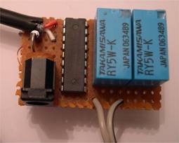
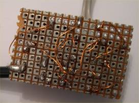
Figure 4 Sender motor control
physical construction
All the
exhibit’s circuits are constructed on breadboard (Figure 4). Connections between the
components are made using shielded copper wire. By heating the wire’s end with
a soldering iron and some solder the wire’s enamel insulation melts away,
allowing it to be soldered to a component’s pin. The power required for all the
experiment’s circuits is obtained from each computer’s USB port, thus doing
away with the need to deploy additional power supply units.
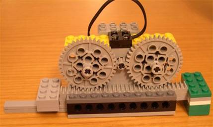
Figure 5 Junction
driver construction. On each end of the rack are
the constraining brakes.
For the
sake of simplicity, the motor runs in an open-loop configuration, i.e. the
controlling software obtains no feedback regarding the junction’s position.
Instead, the movement of the gear that drives the function is physically
constrained on both ends (Figure 5), and the software overcompensates
on the time it allows the motor to run.
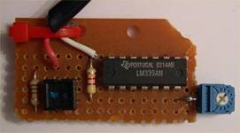

Figure 6 Train sensor board and its mounting
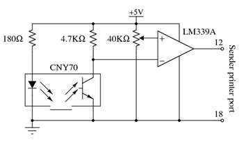
Figure 7 Train sensor board circuit
The sender
side also needs to sense when a train is approaching in order to transmit the
next pixel. This task is performed by a sensor board mounted vertically by the
side of the rails (Figure 6). The sensor circuit (Figure 7) is based on an integrated reflective
optical sensor with transistor output (Vishay 2012). This combines in a single
package a 950nm infrared emitter and a matching phototransistor. The package’s
window contains a daylight blocking filter, thus improving the construction’s
noise immunity. The transistor’s output is fed to a voltage comparator designed
to operate from a single power supply (Fairchild 2012). This is used to convert
the phototransistor’s varying output voltage into a TTL-compatible digital
signal that can be fed as input to the computer’s printer port. The comparator’s
reference voltage is set by means of a trimmer potentiometer allowing the
precise adjustment of the sensor’s triggering condition.
The
sender-side software is written in the Processing
programming language (Read and Fry 2007). The image to transfer (a human stick
figure) is stored in a rectangular array of Boolean values, which is
initialized from an image drawn in the source code using so-called ASCII art.
This provides a visual representation of the figure in the code, as can be seen
in the following code excerpt.
// Initialize the img array from its textual image representation
String simg = " # " +
"###" +
" # " +
" # " +
"# #";
for (int r = 0; r < rows; r++)
for (int c = 0; c < cols; c++)
img[r][c] = (simg.charAt(r * cols + c) == '#');
Programs written in Processing have by default an implicit event and drawing loop, which continuously calls the program’s draw function. To guide the program’s control flow I coded the operation of the draw function as a simple state machine (see Figure 8). The program starts its operation in the Waiting state. Once the detector senses a passing train, it advances the row and column that must be sent, turns on the motor in the appropriate direction, and initializes a timer. In 250ms the state becomes Idle, indicating a state where the program waits for the trim to pass through the function. Two seconds later, the program will enter the Waiting state, waiting for the train to make its next round.
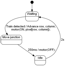
Figure 8 State
transition diagram depicting the program’s
operation
The draw function will also redraw the image
being sent, flashing the pixel in transit with a duty cycle of 500ms. This is done with the following code.
for (int r = 0; r < rows; r++)
for (int c = 0; c < cols; c++) {
if (r == sendingRow && c == sendingCol
&&
((millis() / 500) & 1) == 0) {
if (img[r][c])
// Flash ON pixel
drawFill(color(180, 64, 64));
else
// Flash OFF pixel
drawFill(color(64));
} else if (img[r][c])
// Draw ON pixel
drawFill(color(255, 0, 0));
else
// Draw OFF pixel
drawFill(color(0));
drawPixel(r,
c);
}
The Processing language is based on Java,
which cannot directly access I/O ports. Complicating matters further, modern
versions of the Windows operating system, do not allow any user-mode program to
access I/O ports. These two restrictions were lifted by downloading and
installing the ParallelPort
Java class, which uses the Java native code interface (JNI) to access the
parallel port, and the UserPort
device driver, which allows user-mode programs to access the I/O ports.
Receiver implementation
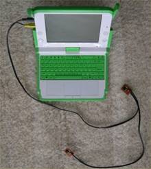
Figure 9 The receiving computer
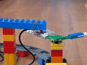
Figure 10 The rotating device mounted on the train and the bit sensor
The
receiving computer is based on a late-prototype of the
One Laptop per Child XO-1 computer, in order to demonstrate the platform’s
effectiveness as an experimentation and teaching aid (Figure
9). Two
sensors are used: a vertically mounted one to detect the approaching train and
a horizontally mounted one to sense the value of the bit that the train is
carrying on its top (Figure
10).
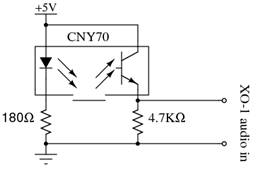
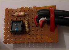
Figure 11 Receiving-end sensor circuit and board
In contrast
to the circuit of the sending-end computer, the receiving-end sensor circuit (Figure 11) does not convert the
phototransistor’s analog voltage level into a digital signal. Instead, it
utilizes a hardware design feature of XO-1 that allows its audio input to be
used as a sensor for analog values. This feature is there to aid
experimentation and does indeed simplify the sensor’s connection. Thus, the two
sensors are directly connected to the XO-1 audio input.
The
receiver’s software was implemented in the Squeak (Ingalls et al 1997) EToys environment (Gaelli et al
2006) as ported to the XO-1 laptop (Freudenberg et al 2009). The XO-1 laptop
port allows EToys to be used from within the XO-1
shell by adopting the look and feel of other OLPC activities, by providing
support for the persistence of programming projects through the environment’s
journal facility rather than files, and by allowing the sharing of projects between
pupils. In addition, the port addresses particularities of the laptop’s
hardware, such as the higher screen resolution, a processor with relatively low
performance (433MHz), a color scheme that is not based on sub-pixel color
components, and the ability of the audio jack to be used for sensor input. This
last feature requires the analog to digital converter hardware to be switched
from AC mode into a DC mode thereby removing the filtering of an audio signal’s
DC component. A new object, called “World Stethoscope” supports the use of the
microphone jack as a sensor.
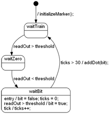
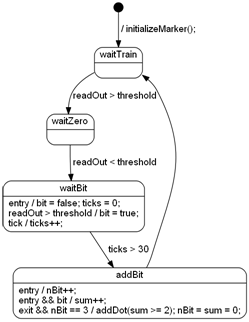
Figure 12 Receiver state machine: plain (left), error correcting (right)
Given that
the EToys’ World Stethoscope object provides only a
single input it is used to handle the input both from the sensor detecting the
train’s approach and the sensor detecting the bit’s value. This is done by
implementing in software what is effectively a frequency modulation decoder.
The software waits for a fixed time interval after a train passes to see if a
“1” bit is detected by the bit value sensor. If the sensor does not detect such
a value, the software assumes that the value is “0”.
The
receiver is implemented as a state machine (see Figure 12 left). In the waitTrain
state the software waits for a train to approach. When the sensor’s read out value rises above
a pre-determined threshold, the software enters into the waitZero
state, where the software waits for the train to move away from the train
sensor. This happens when the sensor’s read out value falls below the threshold
value. At that point the software enters the waitBit state, where it zeroes a tick counter and the bit value and waits
for a bit sensor value to appear. If the sensor’s read out value rises above
the threshold, the bit value is set to true (1). After 30 ticks, a dot (pixel)
with the recorded bit value is added to the image reconstructed on the screen,
and the image’s current coordinates are updated. (The image is transmitted as a
series of pixels; the receiver has hard-coded the image’s dimensions.)
The
experiment also allows the demonstration of error detection and correction. Under
this scheme, each pixel is transmitted three times; at least two “1” values
indicate a pixel with an “on” value, while at least two “0” values indicate a
pixel with an “off” value. Errors can be easily introduced by manually
manipulating the direction of the train’s L-shaped data carrier. The
corresponding state machine diagram is illustrated in Figure 12 (right). An additional state, addBit,
counts the number (nBit) and sum (sum) of the bits received. When three
bits have been received (the train has passed three times from the receiving
station), a pixel is added based on the bits’ sum value, and
the two counters are zeroed.
The EToys
factor
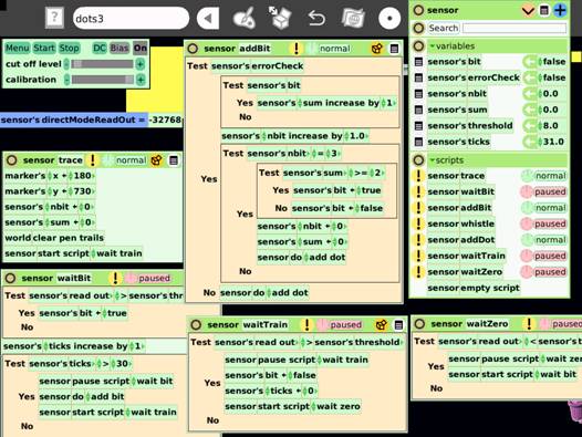
Figure 13 Programming the EToys World Stethoscope object on the XO-1 laptop
Figure 13 illustrates the EToys
programming environment running on the XO-1 laptop. Programming the receiver in
the EToys environment proved to be a productive and
enjoyable experience. The integration of the analog sensor within EToys was a pleasant surprise compared to the pain
associated with the three barriers that needed to be overcome (Processing,
Java, Windows) in order to access the printer port on the sender side.
Furthermore, the World Stethoscope object, whose controller and observer appear
on the top left of Figure 13, made it easy to observe directly
the sensor’s value and create an appropriate threshold for detecting objects.
Interestingly,
there is a one-to-one correspondence between each state of the state machine
that describes the receiving software functioning and an EToys
script. This makes it easy to understand how the state machine functions and to
observe its operation. Scripts in EToys can be
running or paused. Pausing a script and starting
another one is the equivalent of moving from one state to another. During
development it was easy to set the machine to a specific state, simply by
clicking on the corresponding script’s clock icon to have the script begin
“ticking” and thereby made active.
Similarly,
all the variables and states associated with the receiver were easily visible
as a sensor pane (top right on Figure 13). This made it easy to debug the
software during development, but, more importantly, it also allowed me to
explain its operation when the experiment was demonstrated to children. For
instance, it was fascinating to see the tick count begin to decrease once the
train passed through the first sensor. In addition, explaining the error
correction functionality without seeing the corresponding variables would have
been futile.
Experience and lessons
learned
The
experiment was exhibited in a scientific experiment
contest organized by the CAIDA non-profit
organization and the Eugenides Foundation in Athens,
Greece. There it was awarded one of the contest’s three prizes. The stated goal
of the experiment was to demonstrate to children the basic elements of
information theory (Shannon 1948): conversion of an image from analog to
digital form, the transmission of information as bits, the reconstruction of an
image from digital bits, and reliable communication in the presence of errors.
The experiment’s Lego construction and the rapidly moving train attracted many
children to the stand. A large proportion stayed to see the experiment in
action, and many asked questions and appeared to understand the concepts behind
it. Given the types of parents who take the children to science fairs, it was
no surprise that many parents also asked questions, not only about the theory
about behind the experiment, but (mostly) concerning its implementation.
The
experiment’s construction and operation proved to offer something for everyone.
A toddler would look at the rotating train and listen it whistle as it passed
from the receiving station, and even help the construction of the tracks. An
older child could help with the other parts of the Lego construction, and
observe how a train could transmit a picture pixel-by-pixel from one computer
to the other. Those with an interest in programming could observe the receiving
end’s script operation, while the more mathematically inclined would appreciate
the error correction algorithm. The design and soldering of the hardware as
well, the sender implementation in the Processing language, and (probably) the
design of the receiver software were tasks that required an adult.
A need to
involve an adult in the process should not be taken as a negative verdict on EToys. There are many interesting and worthwhile activities
that children without the help of an adult can perform in EToys
in general, and using the World Stethoscope object in particular. Examples
include games, animations, demonstrations, and setups to react to the outside
world. For instance a child could connect a photo-resistor to the XO-1’s input
and have a sun
on a scene rise and set based on the light the resistor receives. Or it could
build a simple alarm, by monitoring a switch to trigger a horn sound. Nevertheless,
the World Stethoscope object could benefit from some polishing to make it more
child-friendly. The elimination of terms like “Bias”, “DC”, and “calibration”
from its user interface and operation, would go a long way toward this
direction. Instead of the various adjustments, the corresponding operations
could be performed transparently behind the scenes based on the input the
object receives.
EToys
proved, once again (see Spinellis, 2008), to be an interesting platform to
demonstrate non-trivial programming concepts. Alan Kay, a driving force behind
Squeak on which EToys runs, has written that to learn
science we “have to find ways to make the invisible visible” (Kay, 2003). This credo
was made possible at many levels during the development of the experiment. Most
obviously children could see the bits carried around on the train making their
way into the picture. At a deeper level, elements of the receiver program were
also visible. The state machine’s states, rather than being hidden behind an
opaque variable, as is usually the case in such implementations (Thomas and
Hunt 2002), were visible as separate scripts implementing the transitions. More
impressively, the active state was also clearly visible during the operation as
the currently running EToys script as a “running”
script, whereas the scripts associated with the other states appeared as
“paused”. Similarly visible were the values of all the
program’s variables (see Figure 13). This allowed be to demonstrate to
observers how the physical world (the train) interacted with the program: how
the program’s variables changed as the train passed through the sensors and the
scripts run and paused.
The experiment’s
modular construction allowed each part to be designed, constructed, and tested
in isolation, allowing the experiment to be gradually implemented in a period
of months. The modular construction also made it easy to transport the
experiment: all parts could fit in a suitcase and could be readily assembled on
site. Switching the junction motor with relays proved to be an easy and
reliable method, in contrast to solid-state approaches tried for another task.
In early phases of the construction the clicking of the relays provided
reassuring feedback that the wiring and the software were working correctly. In
contrast, the detection of objects using infrared sensors proved a tricky
affair. Various integrated and transmitter/receiver pair sensors were tried
with mixed success. Even the sensor used proved to have difficulty operating
within the relatively large distance tolerances of the Lego train set. (The
sensor’s intended use was optoelectronic encoder assemblies, such as index and
coded disk scanning.) In the end, and an adequate signal level was obtained by
covering the Lego parts that the sensor should detect with aluminum foil.
Given the
experiment’s vertical integration and its diverse elements (large scale, normal
scale and Technic Lego parts, electronic sensors and
actuators, laptops, software platforms, software code) the instances where
design choices obviated the need for additional work or elements made a
considerable difference to the project’s viability. These choices included the
saving of two external power supplies by obtaining power from each laptop’s USB
port, the ability of the XO-1 to use its microphone input as a DC voltage
analog to digital converter, and the integration of that converter within the EToys platform. Although each saving may appear trivial,
all together they can add up contributing to a project’s death by a thousand
cuts. As a counterexample, accessing the printer port under Processing involved
code written in C and in x86 assembly language.
Attendees
asked about other projects that could be implemented in a similar way, and
provided some interesting ideas. For instance, one suggested that the receiver
could be implemented using a single sensor that would first detect the train
and then the presence of a “1” bit. In general, mapping microscopic and
extremely fast phenomena onto an observable experiment can have many other
applications. Here are some examples. Demonstrate the functioning of hard-disk
secondary memory by physically storing bits (e.g. Lego blocks) on a large
rotating disk. Make a concrete application out of the hard disk memory by
storing a game’s high score. Show analog-to-digital and digital-to-analog
conversion by loading a discrete number of blocks into a carriage. Explain
printing by taking pictures with a physical camera and printing them using a
motor-driven carriage driving a drawing servo-motor. The possibilities are
endless.
Perhaps the
most important lesson I learned from the experiment was the importance of
accessibility. The experiment provided affordances that allowed direct
manipulation of many aspects of its operation. Children could readily observe
the signal carried atop the train, stop the train to delay the signal, and
change the value of the carried bit to see the effect on the receiving and or
on the error-correction system. On the XO-1 EToys end
children could also see the software’s operation laid bare like a cross-cut of
a working car engine. Although I started with this as a design goal, I feel
fortunate that this aspect worked better than my most optimistic expectations.
References
B. J. Allen-Conn and Kim Rose. Powerful
Ideas in the Classroom Using
Squeak to Enhance Math and Science Learning. Viewpoints
Research Institute, 2003.
Fairchild Semiconductor. LM339/LM339A, LM239A, LM2901: Quad Comparator. Revision
1.0.5, 2012. Available online www.fairchildsemi.com/ds/LM/LM2901.pdf.
B.
Freudenberg, Y. Ohshima, and S. Wallace. Etoys for One Laptop Per Child. In C5 '09: The Seventh International
Conference on Creating, Connecting and Collaborating through Computing, pages
57–64, 2009. (doi:10.1109/C5.2009.9)
M. Gaelli, O. Nierstrasz, and S. Stinckwich. Idioms for composing games with EToys. In C5 '06: The Fourth
International Conference on Creating, Connecting and Collaborating through
Computing, pages 222–231, 2006. (doi: 10.1109/C5.2006.20)
Dan Ingalls, Ted Kaehler, John Maloney, Scott Wallace, and Alan Kay. Back to the future: the story of Squeak, a practical Smalltalk written in itself. In OOPSLA '97: Proceedings of the 12th ACM SIGPLAN Conference on Object-Oriented Programming, Systems, Languages, and Applications, pages 318–326, New York, NY, USA, 1997. ACM Press. (doi:10.1145/263698.263754)
Alan Kay. Our Human
Condition “From Space”. In (Allen-Conn and
Rose, 2003) pp. 73–79.
Newton Lee. Interview with Nicholas Negroponte. Computers in Entertainment, 4(1):3, 2006. (doi:10.1145/1111293.1111298)
Casey
Read and Ben Fry. Processing: A Programming Handbook for Visual
Designers and Artists. MIT Press, Cambridge, MA, 2007.
Claude E. Shannon. A
Mathematical Theory of Communication. Bell System Technical Journal, 27, pages 379–423 and 623–656, July and
October, 1948.
Diomidis Spinellis. The Antikythera mechanism: A computer science perspective. IEEE Computer, 41(5):22–27, May
2008. (doi:10.1109/MC.2008.166)
Texas Instruments. ULN2002A, ULN2003A, ULN2003AI, ULN2004A, ULQ2003A, ULQ2004A: High-voltage
high-current Darlington transistor arrays. December 1976, revised March 2012. Available online www.ti.com/lit/ds/symlink/uln2003a.pdf.
Dave Thomas and Andy Hunt. State Machines. IEEE Software 19(6): 10–12. November/December 2002.
Vishay Intertechnology. CNY70: Reflective Optical Sensor with Transistor Output. Document number 83751. Revision 1.8, July 2012. Available online www.vishay.com/docs/83751/cny70.pdf.